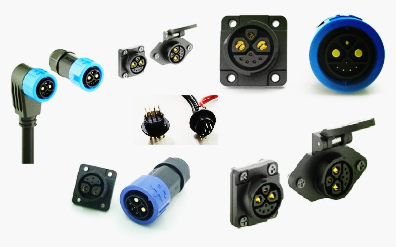
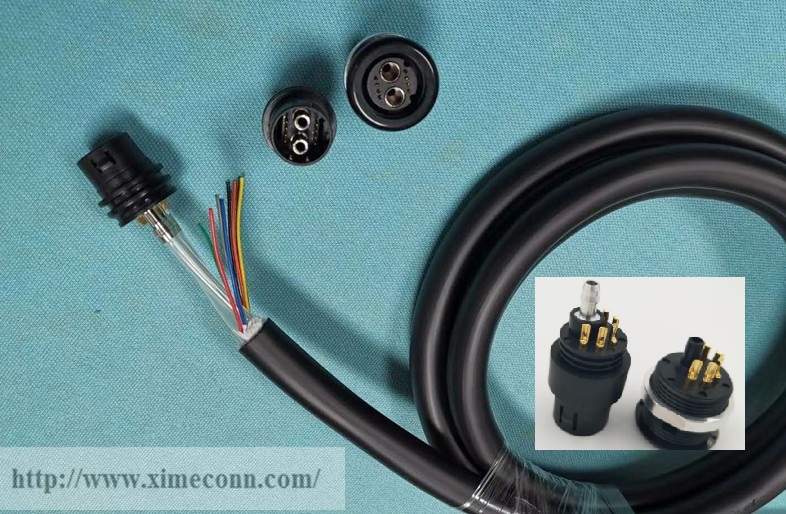
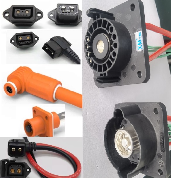
A 2+6 battery connector uses two dedicated power paths and six signal paths inside one housing. That layout suits a battery pack that needs a compact main interface without adding a second control connector and another harness branch. Contact spacing, current duty, and signal integrity must be reviewed as one system because the power pins create heat and electromagnetic noise while the signal pins carry low-voltage information that must remain readable by the BMS or controller. IEC 60684-3-406 supports creepage and clearance principles for hybrid power and signal connectors, and those principles make contact spacing and separation a central review point for a 2+6 interface.
1. Two Power Pins Carry the Main Battery Current Through the Interface
The two power pins form the main current path between the battery pack and the next high-current device, such as a PDU, drive system, or charging interface. The DM80 is available in 100A and 200A options, so the connector family can cover different pack power levels. The selection question is how those ratings line up with continuous current, peak demand, ambient temperature, and wire size. A pack that runs at 100A continuously in a cool enclosure has a different thermal profile from one that pulses to 200A in a sealed battery box. Engineers should treat the power path as a chain: connector contact, terminal crimp, cable gauge, and mating interface. If one link is undersized, the whole path runs hotter. The power pins also set the physical spacing around the high-current zone, so they influence how much room remains for signal routing and locking features.
2. Six Signal Pins Serve BMS and Control Communication in the Same Housing
The six signal pins typically handle BMS and control communication rather than main current. Depending on the pack design, they can carry voltage sense lines, temperature sensor signals, enable or interlock circuits, communication pairs, or other low-voltage control functions. The hybrid topology lets the BMS stay close to the main power interface instead of requiring a separate signal connector and an extra service point. Low-voltage signals are sensitive to the electrical environment around high-current conductors. Good design keeps signal returns organized, avoids unnecessary loops, and maintains separation from the power pins. The six-pin count gives design teams a defined set of signal positions for current BMS needs and future functions, such as service feedback or diagnostic lines.

 +86-15817275200